

A boiler combustion-air fan must deliver the required mass of air at the burner’s pressure, not merely meet a nameplate airflow. You will be able to define the duty point, read a blower curve, and decide whether direct drive suits the installation before comparing equipment.
Key takeaways
- Calculate combustion air from fuel rate, firing value, excess air and air density.
- Add inlet, duct, damper, burner and windbox losses to the fan pressure requirement.
- Use the fan curve and system resistance curve to locate a stable operating point.
- Choose direct drive when required speed, temperature and control range match the motor and impeller.
How a Direct-Drive Blower Feeds an FD Boiler System
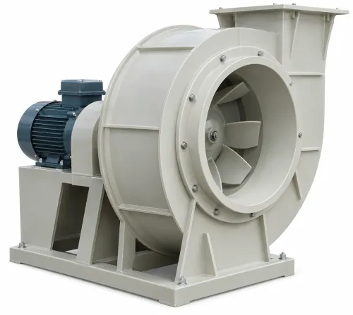
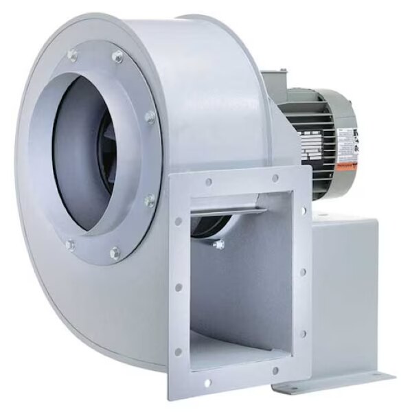
A forced-draft (FD) system pushes combustion air toward the burner. The blower draws air through an inlet louvre or filter, the rotating impeller raises its velocity and pressure, and the scroll converts part of that velocity into static pressure before ductwork carries the air to the windbox and burner register.
The burner then mixes air with fuel and controls the flame pattern.
The direct-drive arrangement mounts the impeller on the motor shaft, removing belts, sheaves, tensioning and belt-slip losses. Its limitation is speed: without a VFD, the impeller follows motor speed, while a belt drive can change speed through pulley ratios. A VFD adds control, but confirm motor cooling, minimum speed, bearing limits and overspeed protection.
FD, ID and balanced-draft duties are different:
| FD | Pressurises combustion-air supply from atmosphere to burner | Air-side temperature and cleanliness govern selection |
|---|---|---|
| ID | Pulls furnace gases through boiler passes and sends flue gas toward the stack | Gas temperature, corrosion, erosion and leakage demand a flue-gas-rated fan |
| Balanced draft | Uses FD pressure and ID suction together to control furnace pressure near its target | Both fans must match the boiler’s airflow and pressure-control range |
Boiler centrifugal blowers therefore need a burner duty point based on air mass flow and required pressure, not volume alone. Air density changes with temperature and altitude. Centrifugal blowers with direct drive chosen for clean ambient air must not be assumed suitable for hot, corrosive ID gas.
Calculate Combustion-Airflow from Fuel, Firing Rate and Air Density
Specify combustion air by mass first, then convert it to the centrifugal blower airflow at the burner inlet. A volumetric figure alone can underfeed the furnace when altitude lowers density or inlet temperature rises.
1. Convert boiler rating to fuel input. If the rating is useful heat output, divide it by the verified boiler efficiency; if it is already fuel input, do not divide it again. Convert that input to fuel mass flow using the fuel’s heating value.
2. Establish the stoichiometric air-fuel ratio from the fuel analysis or burner documentation. Do not substitute a gas-based ratio for oil or solid fuel. Apply the excess-air setpoint as a fraction: m air = m fuel × stoichiometric air-fuel ratio × (1 + excess-air fraction).
3. Correct the mass flow for inlet conditions. Calculate air density with rho = absolute pressure ÷ (air gas constant × absolute temperature). Altitude reduces absolute pressure; hotter inlet air reduces density. Then calculate actual volume as V = m air ÷ rho.
4. Specify the result at the burner’s required pressure, stating whether the airflow is actual inlet cubic metres per second or a standard-condition value. Give the burner manufacturer the fuel composition, firing range, excess-air target and combustion-efficiency basis; its combustion curve and boiler safety controls set the final duty point.
A blower that delivers the right volume at sea level can deliver too little oxygen at altitude or on a hot day. Check the motor and drive against the corrected mass flow, density and pressure rather than relying on a catalogue airflow alone.
Build the Pressure Requirement from the Complete Air Path
Select boiler centrifugal blowers at the intersection of the required centrifugal blower airflow and the complete system-resistance curve. At that airflow, calculate static-pressure duty as the burner’s required inlet pressure plus every upstream loss, rather than choosing a fan from volume alone.
- Inlet louvre, filter and silencer pressure drop at the design airflow
- Duct friction and losses through elbows, transitions and flexible connectors
- Damper pressure drop at its operating position
- Windbox and burner-register resistance
- Burner pressure drop specified by the burner manufacturer
- Furnace-side backpressure that the forced-draft air must overcome
Express the result in one pressure basis, such as pascals, and use the fan curve’s stated static-pressure definition. Do not add total-pressure losses to static pressure without checking how the manufacturer reports the curve.
Add a design margin only after identifying the actual dirty-filter, damper and burner conditions; an arbitrary margin can push the fan toward an unstable operating region.
For turbulent ductwork, resistance rises approximately with the square of flow. Represent the system as ΔPsystem = ΔPfixed + KQ², then plot that curve against the blower curve. The crossing point is the expected duty point.
Check it at the air density, altitude and temperature of operation: those conditions change both pressure performance and motor power. Verify the burner’s mass-flow and pressure requirements at each firing condition, because a fan that reaches volume at low resistance can still fail to deliver combustion air at the burner.
Use the Fan Curve to Find a Stable Operating Point
Choose the operating point where the centrifugal blower performance curve intersects the complete system-resistance curve. That intersection gives the actual centrifugal blower airflow and pressure together; selecting a nominal airflow alone can leave the fan short of pressure or operating near stall, causing separation, pulsation, vibration, noise and damage.
| Curve item | What to compare | What it tells you |
|---|---|---|
| Airflow | Required volume against the curve’s flow axis | Confirms the blower reaches combustion demand at the stated air density and temperature. |
| Pressure | Required static or total pressure on the same basis as the curve | Shows whether the fan overcomes burner, duct, damper and filter resistance. |
| Efficiency | Peak and efficiency at the intersection, using the same gas density, speed and AMCA 210 test basis | Avoids treating an isolated percentage as a valid comparison. |
| Brake horsepower | Shaft-power curve at the operating point, including maximum-flow conditions | Sets the motor and drive rating; fan-law estimates do not replace this check. |
| Shutoff pressure | Pressure at zero airflow | Identifies the closed-damper limit, not a permissible operating point. |
| Surge or stall risk | Manufacturer’s tested stable operating region around the intersection | Rejects points near unstable low-flow operation, where pressure can pulsate and bearings can suffer. |
Check the point after control-valve movement, filter loading and boiler turndown, not only at design load. A speed change also shifts the curve: at 80% speed, airflow is about 80%, pressure 64% and power 51%, assuming constant density and unchanged geometry.
Keep the operating point inside the manufacturer’s tested region rather than targeting peak efficiency alone.
Choose Direct Drive When Speed, Temperature and Controls Align
Choose direct drive when the required impeller speed matches a standard motor or a motor controlled by a VFD, and when you value a compact assembly without belts, sheaves, tensioning or belt contamination.
It is a poor choice when one motor must cover widely different impeller speeds or when the motor cannot tolerate the surrounding gas temperature.
Arrangement | Speed and maintenance | Temperature and control Direct drive | Impeller speed follows motor speed; no belt-slip or belt-tension maintenance | VFD control is available, but motor cooling and overspeed limits require checking Belt drive | Pulley ratios provide wider speed selection; belts require alignment and replacement | Motor can be positioned away from hot gas, giving more thermal flexibility Direct-drive blower applications suit clean, moderate-temperature FD air when compactness and repeatable speed matter.
For hot, dusty or corrosive gas, specify a shaft seal, isolated bearing housing or cooling barrier; otherwise heat and deposits can damage nearby bearings.
Before approving the arrangement, verify:
- Motor rated power, service factor, insulation, cooling at minimum speed and allowable overspeed.
- VFD current, frequency range, carrier settings, minimum speed and fault protection.
- Shaft diameter, key and hub fit, rotor balance and critical-speed margin.
- Bearing temperature, lubrication, load rating and inspection access.
- Foundation stiffness, soft-foot correction, shaft alignment, duct expansion joints and allowable nozzle loads.
Ask Sys Enterprises to document these limits against the actual boiler gas temperature, dust, condensation cycle, airflow and static pressure—not only the motor nameplate rating.
Related products
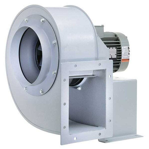 | Centrifugal blowers Sys Enterprises offers a robust range of Centrifugal Blowers in both Direct Drive and Belt Drive configurations, designed for high-pressure and... View product → |
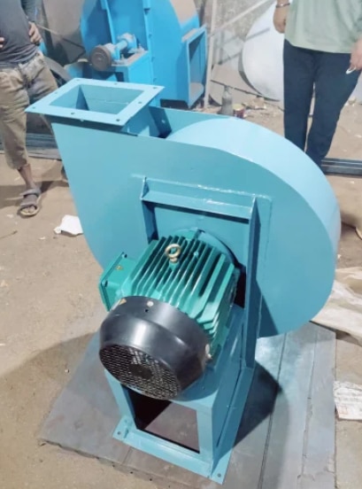 | Centrifugal blowers ₹20000 Manufacturer & Supplier We are a leading manufacturer and supplier of Boiler Forced Draft (FD) Fans, engineered to supply a continuous flow of... View product → |
Frequently asked questions
How does a direct-drive blower feed a boiler FD system?
It draws air through the inlet, raises velocity and pressure with an impeller, then sends air through the ductwork to the windbox and burner register.
How do you calculate required boiler combustion airflow?
Start with fuel firing rate and stoichiometric air demand, apply the selected excess-air percentage, then convert mass flow to volume using air density at operating conditions.
What pressure must a boiler centrifugal blower provide?
Add pressure losses across the inlet louvre or filter, impeller and scroll, ducts, bends, dampers, windbox, burner register and any other restrictions.
When are direct-drive centrifugal blowers suitable for boiler applications?
They suit systems where the required speed, air temperature, motor rating and control range align without needing belt-ratio adjustment.